


 English
 русский
 عربى
عربى 中文简体
中文简体
Content
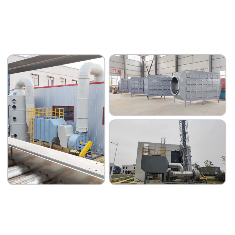
Environmental engineers and plant managers rely on activated carbon adsorption equipment to control air emissions and purify process streams. This technology removes volatile organic compounds, odors, and hazardous contaminants through surface adsorption phenomena. Understanding the engineering principles behind these systems supports effective procurement and operational decisions.
Understanding Activated Carbon Adsorption Equipment
Activated carbon adsorption equipment uses porous carbon media to capture gas-phase contaminants from air or vapor streams. The activation process creates internal surface areas between 800 and 1,500 square meters per gram. This massive surface area provides adsorption sites for organic molecules through van der Waals forces.
Two mechanisms govern contaminant removal. Physical adsorption involves weak intermolecular attractions between carbon surfaces and adsorbate molecules. Chemical adsorption creates stronger bonds through surface oxidation or functional group interactions. Most industrial applications rely primarily on physical adsorption, which remains reversible and enables carbon regeneration.
Types of Industrial Carbon Adsorption Systems
Engineers select system configurations based on airflow rates, contaminant concentrations, and regeneration requirements. Each design offers distinct advantages for specific industrial applications.
Fixed Bed Adsorbers
Fixed bed systems pass contaminated air through stationary carbon beds. These units provide simple operation and high removal efficiency for continuous processes. Bed depths typically range from 0.3 to 1.5 meters, depending on contact time requirements. Multiple beds in parallel or series configurations allow continuous operation during carbon replacement or regeneration cycles.
Fluidized Bed Systems
Fluidized beds suspend carbon particles in upward-flowing air streams. This configuration enhances mass transfer rates and reduces pressure drop compared to fixed beds. Fluidized systems suit high-volume applications with moderate contaminant concentrations. The continuous mixing action prevents channeling and ensures uniform carbon utilization.
Rotary Concentrator Wheels
Rotary concentrators use honeycomb-structured carbon wheels to adsorb contaminants from large air volumes. Desorption zones regenerate the carbon using heated air, concentrating contaminants into smaller streams for thermal oxidation. This technology reduces energy consumption by 60-80% compared to direct thermal oxidation of full air volumes.
System configuration comparison for engineering selection:
| Parameter | Fixed Bed | Fluidized Bed | Rotary Wheel |
| Airflow Capacity | 1,000-50,000 CFM | 10,000-100,000 CFM | 10,000-200,000 CFM |
| Typical VOC Concentration | 50-5,000 ppm | 100-10,000 ppm | 50-1,000 ppm |
| Removal Efficiency | 90-99% | 85-95% | 85-95% |
| Pressure Drop | 2-10 in H2O | 1-4 in H2O | 0.5-2 in H2O |
| Regeneration Capability | Yes (in situ or off-site) | Yes (continuous) | Yes (continuous) |
Design Parameters for Engineers
Proper sizing of an ndustrial activated carbon adsorber design requires analysis of multiple process variables. Engineers must balance removal efficiency against operational costs and system footprint.
Breakthrough Curve Analysis
The breakthrough curve plots outlet concentration versus operating time. Breakthrough occurs when outlet concentrations exceed regulatory limits or process requirements. Engineers design systems to operate at 50-75% of breakthrough time, providing safety margins for process upsets. The shape of the curve depends on the adsorption isotherm characteristics and mass transfer rates.
Contact Time and Bed Depth
Empty bed contact time (EBCT) equals bed volume divided by airflow rate. VOC applications typically require 2-5 seconds of EBCT for adequate removal. Higher molecular weight compounds or lower concentrations may require extended contact times up to 10 seconds. Bed depth calculations must account for the mass transfer zone length, which represents the active adsorption region.
Pressure Drop Considerations
Pressure drop across carbon beds increases with bed depth, air velocity, and carbon particle size. Granular carbons generate 2-5 inches of water column pressure drop per foot of bed depth at typical face velocities. System fans must overcome this resistance while maintaining design airflow rates. Engineers optimize between carbon particle size (affecting pressure drop) and adsorption kinetics (favored by smaller particles).
Design parameter ranges for common industrial applications:
| Application | EBCT (seconds) | Face Velocity (ft/min) | Bed Depth (ft) | Carbon Type |
| Solvent Recovery | 3-5 | 20-40 | 2-4 | Pellet 4mm |
| Odor Control | 2-3 | 30-60 | 1-2 | Granular 4x6 |
| Gas Purification | 5-10 | 10-20 | 3-6 | Pellet 3mm |
| HVAC Systems | 0.5-2 | 100-300 | 0.5-1 | Impregnated |
Carbon Media Selection
Carbon's physical properties significantly affect system performance. Engineers evaluate pore size distribution, particle size, and surface chemistry during specification.
Granular vs Pellet Activated Carbon Performance
Granular vs pellet activated carbon performance differs in pressure drop, mechanical strength, and adsorption kinetics. Granular carbons offer lower cost and higher surface area but generate greater pressure drop. Pelletized carbons provide uniform flow distribution and higher mechanical strength for fluidized applications.
Pore structure determines adsorption capacity for specific contaminants. Micropores (less than 2 nanometers) adsorb small molecules like methanol and acetone. Mesopores (2-50 nanometers) capture larger VOCs such as toluene and xylene. Macropores facilitate transport into smaller pore structures.
Impregnated Carbon for Special Applications
Chemical impregnation extends carbon capabilities beyond physical adsorption. Acid-impregnated carbons remove ammonia and amines. Base-impregnated versions capture hydrogen sulfide and sulfur dioxide. Potassium iodide impregnation enhances mercury removal efficiency to 99.9% in coal combustion applications.
Industrial Applications
Activated Carbon Filter System for VOC Removal
The activated carbon filter system for VOC removal serves as the primary control technology for surface coating operations, printing facilities, and chemical manufacturing. These systems capture solvents including acetone, ethanol, and aromatic hydrocarbons. Design engineers must consider the heat of adsorption, which can raise bed temperatures 20-50 degrees Fahrenheit above inlet conditions.
System sizing requires accurate emission characterization. Engineers conduct stack testing or process mass balances to determine VOC loading rates. Safety factors of 1.5 to 2.0 accommodate production variations and seasonal temperature effects on adsorption capacity.
Activated Carbon Air Purification System Sizing for Manufacturing
Activated carbon air purification system sizing for manufacturing facilities follows established engineering protocols. The process involves:
- Characterizing contaminant species and concentrations
- Determining required removal efficiency based on permits
- Calculating carbon working capacity from adsorption isotherms
- Establishing bed geometry for target contact time
- Specifying fan capacity for airflow and pressure requirements
Manufacturing environments with multiple emission sources may require centralized or distributed treatment approaches. Centralized systems offer economies of scale but require extensive ductwork. Point-source treatment reduces transport distances and allows process-specific optimization.
Operation and Maintenance
Effective operation extends carbon life and maintains removal efficiency. Monitoring systems track pressure drop, outlet concentrations, and operating temperatures.
Activated Carbon Regeneration Methods: Thermal vs Chemical
Activated carbon regeneration method,s thermal processi,ng remains the industry standard. Thermal regeneration heats spent carbon to 1,400-1,800 degrees Fahrenheit in controlled atmosphere furnaces. This process volatilizes adsorbed contaminants and restores 90-95% of the original adsorption capacity. Steam regeneration at 200-400 degrees Fahrenheit suits applications with volatile, non-polymerizing contaminants.
Chemical regeneration uses acid or base washing to remove specific contaminant classes. This approach costs less than thermal processing but achieves only 70-80% capacity restoration. Chemical regeneration suits specialized applications where thermal processing damages the carbon structure.
Carbon replacement becomes necessary after 5-15 regeneration cycles, depending on contaminant characteristics. Polymerizing compounds or high-boiling residues permanently block pore structures. Engineers establish replacement schedules based on breakthrough monitoring rather than theoretical cycle limits.
Frequently Asked Questions
How do I determine the correct carbon type for my application?
Carbon selection depends on contaminant molecular weight, concentration, and required removal efficiency. Low molecular weight compounds (under 50 g/mol) require high micropore volume. High concentrations favor carbons with extensive mesoporosity. Engineers request adsorption isotherm data from suppliers for specific contaminant mixtures. Pilot testing with 100-200 pound carbon samples validates performance predictions.
What is the typical service life of activated carbon in industrial systems?
Carbon service life ranges from 6 months to 3 year,s depending on contaminant loading and regeneration frequency. Continuous monitoring of outlet concentrations identifies breakthrough before regulatory exceedance. Thermal regeneration extends total carbon life to 3-5 years across multiple cyclesNon-regenerativele applications require scheduled replacement based on calculated working capacity.
Can activated carbon adsorption equipment handhigh-humidityity air streams?
Water vapor competes with organic contaminants for adsorption sites. Relative humidity above 50% reduces VOC capacity by 20-40%. Engineers specify moisture removal upstream using cooling coils or desiccant systems when inlet humidity exceeds design limits. Some applications use hydrophobic carbon formulations or operate at elevated temperatures to minimize moisture effects.
References
- EPA 456/R-95-003: VOC Control/Destruction Efficiency Test Protocols for Carbon Adsorption Systems. U.S. Environmental Protection Agency, 1995.
- AWWA B604-18: Granular Activated Carbon. American Water Works Association, 2018.
- ASTM D2652: Standard Terminology Relating to Activated Carbon. ASTM International, 2011.
- Bandosz, T.J. (2006). Activated Carbon Surfaces in Environmental Remediation. Academic Press, Elsevier.
- EPA Air Pollution Control Cost Manual: Chapter 4, Carbon Adsorption. U.S. Environmental Protection Agency, 6th Edition, 2002.


