


 English
 русский
 عربى
عربى 中文简体
中文简体
Content
Activated carbon adsorption equipment is an industrial air and water purification system that uses the exceptionally high surface area and pore structure of activated carbon to remove organic pollutants, volatile organic compounds (VOCs), odorous gases, and dissolved contaminants from gas or liquid streams through physical and chemical adsorption mechanisms. As environmental regulations tighten globally and industrial emission standards become increasingly stringent, activated carbon adsorption equipment has become one of the most widely deployed end-of-pipe treatment technologies across pharmaceutical, chemical, electronics, printing, coatings, and wastewater treatment industries.
This engineer-level guide covers the complete technical and commercial landscape of activated carbon adsorption equipment — from adsorption fundamentals and system configurations to regeneration methods, selection criteria, regulatory compliance, and key considerations for B2B procurement teams sourcing industrial-scale systems.
1. How Activated Carbon Adsorption Equipment Works
1.1 Adsorption Mechanism: Physical vs Chemical Adsorption
The operating principle of activated carbon adsorption equipment is based on the tendency of molecules in a fluid phase to accumulate at the surface of a solid adsorbent. Two distinct mechanisms govern this process:
- Physical adsorption (physisorption): Driven by van der Waals intermolecular forces between the adsorbate molecule and the carbon surface. No chemical bonds are formed, meaning the process is fully reversible — the adsorbed molecule can be desorbed by reducing partial pressure or increasing temperature. Physisorption is the dominant mechanism in most VOC and organic gas removal applications and is the basis for the regenerability of activated carbon adsorption equipment. Adsorption capacity is proportional to the adsorbate's molecular weight and boiling point: heavier, higher-boiling-point VOC molecules adsorb more strongly than lighter, lower-boiling-point species.
- Chemical adsorption (chemisorption): Involves formation of chemical bonds between the adsorbate and surface functional groups on the carbon. This mechanism produces higher adsorption capacity for specific target compounds (e.g., hydrogen sulfide, mercury vapor, acid gases) but is generally irreversible — chemically adsorbed species cannot be removed by thermal regeneration, making carbon replacement rather than regeneration the required response to saturation. Impregnated activated carbons (loaded with KI, KOH, H3PO4, or metallic compounds) exploit chemisorption for specific contaminant removal.
1.2 Role of Pore Structure: Micropore, Mesopore, Macropore
The extraordinary adsorption capacity of activated carbon — specific surface areas of 500–2,000 m²/g compared to 1–5 m²/g for conventional filter media — is a direct consequence of its highly developed internal pore network. The IUPAC classification defines three pore size categories, each serving a distinct function in the adsorption process:
| Pore Type | Diameter Range | Function in Adsorption | Target Contaminants |
|---|---|---|---|
| Micropores | <2 nm | Primary adsorption sites — highest surface energy and capacity | Small organic molecules, VOCs, solvents (MW <300 g/mol) |
| Mesopores | 2–50 nm | Transport pathways to micropores; adsorption of larger molecules | Dyes, larger organic molecules, some pesticides |
| Macropores | >50 nm | Highway network for rapid adsorbate transport into the carbon particle | Not primary adsorption sites — diffusion role only |
For activated carbon adsorption equipment for VOC removal, carbons with high micropore volume (>0.4 cm³/g) and BET surface area exceeding 1,000 m²/g are specified to maximize adsorption capacity per unit carbon mass. For activated carbon adsorption equipment for wastewater treatment, mesopore volume becomes more important to accommodate the larger dissolved organic molecules and humic substances typically present in industrial effluents.
1.3 Breakthrough Curve and Saturation Point
The breakthrough curve is the fundamental performance metric for any activated carbon adsorption equipment system operating in continuous flow mode. As contaminated gas or liquid passes through the carbon bed, adsorption occurs progressively — the inlet layers of carbon saturate first, and the mass transfer zone (MTZ) — the region of active adsorption — migrates toward the bed outlet over time. Breakthrough is defined as the moment when the outlet contaminant concentration reaches a defined fraction of the inlet concentration (typically 5–10% for VOC systems, or the regulatory emission limit, whichever is more stringent).
Critical breakthrough curve parameters that determine system design and operational decisions include:
- Breakthrough time (t_b): The time from operation start to breakthrough — determines the regeneration or carbon replacement interval and directly governs operating cost.
- Saturation time (t_s): The time to complete bed saturation — the ratio t_b/t_s defines the sharpness of the breakthrough front. Sharp fronts (ratio approaching 1.0) indicate efficient carbon utilization; gradual fronts indicate axial dispersion, channeling, or poor bed design.
- Carbon utilization efficiency: The fraction of total carbon capacity actually utilized before breakthrough — typically 50–80% for well-designed fixed-bed systems. Lower efficiency indicates over-designed beds or poor flow distribution.
1.4 Key Performance Indicators: Adsorption Capacity, Bed Depth, Contact Time
System engineering of activated carbon adsorption equipment centers on three interdependent design variables:
- Adsorption capacity (q, mg/g or kg/kg): The mass of contaminant adsorbed per unit mass of carbon at equilibrium, defined by the adsorption isotherm (Langmuir or Freundlich model) for the specific adsorbate-carbon system at operating temperature. Published isotherm data from carbon manufacturers provides the starting point for bed sizing calculations.
- Bed depth (L, m): Minimum bed depth is determined by the mass transfer zone length — the bed must be at least 1.5–2.0× the MTZ length to achieve the target breakthrough concentration. Deeper beds increase contact time, improve outlet concentration, and extend breakthrough time at the cost of higher pressure drop.
- Empty Bed Contact Time (EBCT, minutes): The ratio of bed volume to volumetric flow rate — the single most important sizing parameter for activated carbon adsorption equipment. Typical EBCT values are 0.1–0.5 seconds for gas-phase VOC systems and 5–30 minutes for liquid-phase wastewater treatment systems. Longer EBCT improves removal efficiency but increases capital cost (larger vessel) and carbon inventory.
2. Types of Activated Carbon Adsorption Equipment
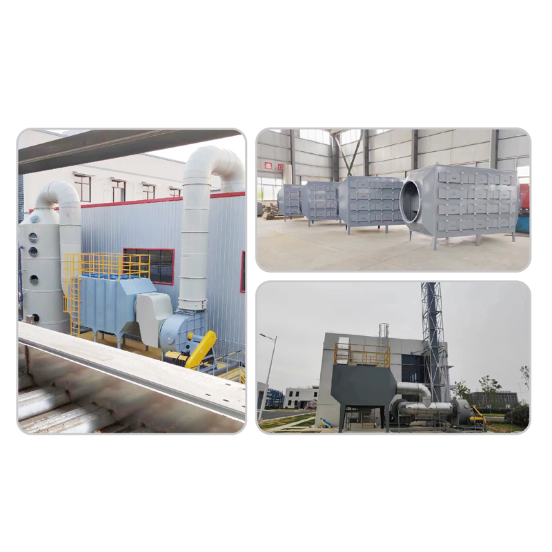
2.1 Fixed-Bed Activated Carbon Adsorption Tower
The fixed-bed adsorption tower is the most widely deployed configuration of activated carbon adsorption equipment in industrial applications. Carbon is packed as a stationary bed within a pressure vessel; contaminated gas or liquid flows through the bed in a defined direction (typically downflow for liquids, upflow or downflow for gases) and clean effluent exits from the opposite end. Fixed-bed systems are operated in either single-bed or multi-bed (lead-lag) configurations:
- Single-bed systems: Simplest configuration — lowest capital cost but requires process shutdown for carbon regeneration or replacement. Suitable for batch processes or applications with infrequent regeneration requirements.
- Dual-bed lead-lag systems: Two beds operate in series — the lead bed adsorbs the majority of contaminant load while the lag bed acts as a polishing stage and early warning of lead bed breakthrough. When the lead bed is saturated, it is taken offline for regeneration while the lag bed becomes the new lead and a freshly regenerated bed enters as the new lag. This configuration enables continuous operation without process interruption — the standard design for industrial continuous emission control applications.
- Multiple parallel beds: Three or more beds in parallel rotation — one adsorbing, one regenerating, one cooling/standby. Used for high-flow applications where a single bed would be impractically large or where continuous operation with overlapping regeneration cycles is required.
2.2 Moving-Bed and Rotating Wheel Adsorption Systems
For applications requiring continuous operation with low pressure drop and high volumetric flow rates — particularly large-volume, low-concentration VOC streams — moving-bed and rotating adsorption wheel systems offer advantages over fixed-bed configurations:
- Moving-bed adsorbers: Carbon granules move continuously downward through the adsorption zone by gravity while contaminated gas flows upward countercurrently. Saturated carbon is continuously withdrawn from the bottom and transferred to a regeneration unit; regenerated carbon is returned to the top. This configuration achieves near-theoretical carbon utilization efficiency and eliminates the breakthrough limitation of fixed-bed systems.
- Rotating adsorption wheel (honeycomb rotor): A cylindrical rotor packed with honeycomb-structured activated carbon or zeolite rotates slowly (1–10 RPH) through alternating adsorption and desorption sectors. This design is particularly effective for large-volume, low-concentration VOC streams (inlet concentration 10–500 mg/m³) where it concentrates the VOC load by a factor of 10–30× before routing the concentrated stream to a downstream thermal oxidizer — reducing oxidizer operating costs substantially.
2.3 Industrial Activated Carbon Adsorption Tower Design — Key Parameters
Engineering an industrial activated carbon adsorption tower design requires specification of the following interdependent parameters to meet emission targets reliably across the full range of operating conditions:
| Design Parameter | Typical Range (Gas Phase) | Typical Range (Liquid Phase) | Engineering Significance |
|---|---|---|---|
| Superficial velocity (u) | 0.2–0.5 m/s | 5–15 m/h | Governs pressure drop and mass transfer coefficient |
| Bed depth (L) | 0.3–1.5 m | 1.0–3.0 m | Must exceed 1.5× MTZ length for target efficiency |
| EBCT | 0.1–0.5 s | 5–30 min | Primary sizing parameter for removal efficiency |
| Carbon particle size | 4×8 mesh (2.4–4.8 mm) | 8×30 mesh (0.6–2.4 mm) | Smaller particles: better kinetics, higher pressure drop |
| Pressure drop (ΔP) | 500–2,000 Pa/m | 0.5–2.0 bar/m | Determines fan/pump energy consumption |
| Temperature range | 10–50°C (optimal) | 5–40°C (optimal) | Higher temperature reduces adsorption capacity |
| Relative humidity (gas phase) | <70% RH preferred | N/A | Water vapor competes with VOC for adsorption sites above 70% RH |
2.4 Modular vs Custom-Engineered Systems
The procurement decision between modular standard units and custom-engineered activated carbon adsorption equipment is determined by the complexity and scale of the application:
- Modular systems: Pre-engineered, factory-assembled units available in standard flow rate and carbon inventory sizes. Shorter lead time (4–8 weeks vs 12–24 weeks for custom), lower engineering cost, and easier replacement part availability. Best suited for applications where flow rate, concentration, and target efficiency fall within the standard unit's specification range.
- Custom-engineered systems: Designed specifically for the client's process conditions, site constraints, and regulatory requirements. Required for non-standard flow rates, high-temperature or high-humidity streams, multi-component VOC mixtures requiring specialized carbon selection, or integrated systems incorporating pre-treatment, regeneration, and downstream treatment in a single engineered solution. Higher upfront engineering and fabrication cost is offset by optimized performance, lower lifetime operating cost, and guaranteed regulatory compliance.

3. Core Applications by Industry
3.1 Activated Carbon Adsorption Equipment for VOC Removal
Activated carbon adsorption equipment for VOC removal is the primary application driving global market demand for this technology. Industrial VOC emissions — from solvents, coating operations, pharmaceutical synthesis, printing, rubber processing, and chemical manufacturing — are subject to increasingly stringent regulatory limits under China's GB 16297, the EU's Industrial Emissions Directive (IED), and the US EPA's National Emission Standards for Hazardous Air Pollutants (NESHAP).
Key performance requirements for activated carbon adsorption equipment for VOC removal include:
- Removal efficiency: Typically >95% for regulatory compliance in China's key industry sectors (GB 37822-2019 requires total VOC outlet concentration ≤60 mg/m³ for most industries); >98% may be required for hazardous air pollutant (HAP) removal in pharmaceutical and chemical applications.
- Inlet concentration range: Fixed-bed carbon adsorbers are optimized for inlet VOC concentrations of 300–5,000 mg/m³. Below 300 mg/m³, carbon utilization per regeneration cycle drops, increasing operating cost. Above 5,000 mg/m³, fire and explosion risk from exothermic adsorption heat release requires careful thermal management and safety interlock design.
- Solvent recovery integration: For high-value solvents (MEK, toluene, ethyl acetate, DMF), steam-regenerated activated carbon adsorption equipment for VOC removal allows the desorbed solvent to be recovered by condensation and reused — converting an emission control cost into a raw material recovery revenue stream that can offset 30–70% of system operating costs.
3.2 Activated Carbon Adsorption Equipment for Wastewater Treatment
Activated carbon adsorption equipment for wastewater treatment addresses the removal of dissolved organic compounds, trace pharmaceuticals, pesticides, dyes, heavy metal complexes, and taste-and-odor compounds from industrial effluents and drinking water that are resistant to biological treatment processes. The key performance advantage of activated carbon over biological treatment for these applications is its non-selectivity — activated carbon adsorbs virtually all organic compounds simultaneously, regardless of their biodegradability.
Industrial wastewater treatment applications include:
- Pharmaceutical effluent polishing: Removal of active pharmaceutical ingredients (APIs), intermediates, and residual solvents to concentrations below detection limits prior to discharge. Required by increasingly stringent pharmaceutical wastewater discharge standards in China (GB 21904) and Europe.
- Dyeing and textile wastewater: Decolorization of reactive dye effluents with COD reduction from 200–500 mg/L to <50 mg/L. Activated carbon is particularly effective for recalcitrant azo dyes that resist biological degradation.
- Electronics and semiconductor rinse water: Removal of trace organic solvents (IPA, acetone, NMP) from high-purity rinse water streams to enable water reuse and reduce discharge volume.
- Drinking water advanced treatment: Removal of disinfection byproduct precursors, taste-and-odor compounds (geosmin, 2-MIB), and micropollutants as a tertiary polishing step after conventional treatment.
3.3 Pharmaceutical, Chemical, and Printing Industries
These three sectors collectively represent the highest-value market segment for activated carbon adsorption equipment due to the combination of high-value solvent streams (justifying solvent recovery investment), stringent regulatory requirements (driving high removal efficiency specifications), and complex multi-component VOC mixtures (requiring expert system design and carbon selection):
- Pharmaceutical manufacturing: Synthesis, formulation, and coating operations generate solvent-laden exhaust streams containing ethanol, IPA, acetone, methylene chloride, and other HAPs. Industrial activated carbon adsorption tower design for pharmaceutical applications must address solvent mixture compatibility, explosion-proof electrical classification (ATEX Zone 1 or 2), and GMP documentation requirements.
- Chemical manufacturing: Process vents, reactor exhaust, and storage tank breathing losses contain a wide range of organic compounds. Carbon selection must account for competitive adsorption between mixture components and potential for heat-of-adsorption temperature rise with concentrated streams.
- Printing and packaging: Flexographic, gravure, and offset printing operations generate large volumes of solvent-laden exhaust (toluene, ethyl acetate, isopropanol). Solvent recovery via steam-regenerated carbon adsorption is economically compelling at the solvent loadings typical of high-speed printing operations.
3.4 Electronics, Photovoltaics, and Rubber Processing
Electronics and photovoltaic manufacturing generate process exhaust containing NMP (N-methyl-2-pyrrolidone), DMF (dimethylformamide), and other high-boiling solvents from coating and lamination operations. These solvents have high adsorption affinity for activated carbon (high boiling point = strong adsorption) and significant economic recovery value — making activated carbon adsorption equipment with solvent recovery the preferred technology over thermal oxidation for these applications. Rubber processing and vulcanization operations emit sulfur compounds, hydrocarbons, and particulate-laden gases requiring pre-filtration before carbon adsorption to prevent premature bed fouling.
4. Regeneration of Activated Carbon Adsorption Equipment
4.1 Steam Regeneration — Process and Energy Requirements
Steam regeneration is the most widely used method for regeneration of activated carbon adsorption equipment in solvent recovery applications. Low-pressure steam (110–140°C, 0.05–0.3 MPa) is passed through the saturated carbon bed, providing the thermal energy required to desorb adsorbed VOCs (desorption is endothermic — the reverse of exothermic adsorption). The desorbed VOC-steam mixture exits the bed and is condensed in a heat exchanger; phase separation (decantation) separates the recovered solvent from the condensate water.
Key steam regeneration parameters:
- Steam-to-solvent ratio: Typically 2–5 kg steam per kg solvent desorbed, depending on the solvent's adsorption affinity and the bed's residual loading target after regeneration.
- Residual loading after regeneration: Not all adsorbed solvent is removed in each regeneration cycle — typically 10–30% of the pre-regeneration loading remains as "heel." This heel accumulates over successive cycles until equilibrium is reached, defining the carbon's working capacity as the difference between breakthrough loading and equilibrium heel loading.
- Carbon drying after steam regeneration: The carbon bed retains significant moisture after steam regeneration, which reduces available adsorption capacity for subsequent cycles. Hot air drying (60–100°C) or inert gas purge is required before returning the bed to service.
4.2 Thermal / Hot Gas Regeneration
For applications where steam introduction is undesirable — water-sensitive solvents, or systems where solvent-water separation is uneconomical — hot inert gas (nitrogen at 150–250°C) or hot air regeneration is used. Hot gas regeneration achieves lower residual heel than steam regeneration (since no water is introduced to compete for adsorption sites during cooling) but requires more complex gas recirculation infrastructure. This method is preferred for ketone solvents (MEK, MIBK) that form explosive peroxides on contact with water, and for high-boiling solvents where steam condensation temperatures are insufficient for complete desorption.
4.3 Vacuum Desorption and Nitrogen Purge Methods
Vacuum desorption reduces the partial pressure of adsorbed species above the carbon bed, driving desorption at lower temperatures than thermal methods. Combined vacuum-thermal regeneration (applying vacuum simultaneously with moderate heating to 80–120°C) achieves the lowest residual heel of any regeneration method and is specified for high-value solvents where maximum recovery yield is economically critical. Nitrogen purge regeneration — flowing heated nitrogen through the bed to strip adsorbed VOCs — is used for thermally sensitive compounds that would degrade at steam regeneration temperatures and for small-scale systems where steam generation infrastructure is not available.
4.4 Regeneration Cycle Management and Carbon Replacement Thresholds
Effective regeneration of activated carbon adsorption equipment requires systematic cycle management to track carbon performance degradation and determine optimal replacement timing:
| Regeneration Method | Typical Cycle Duration | Carbon Lifetime (cycles) | Residual Heel (% of fresh capacity) | Best Application |
|---|---|---|---|---|
| Steam regeneration | 4–8 hours | 500–1,000 cycles | 10–30% | Solvent recovery (alcohol, ketone, ester) |
| Hot gas (N₂) regeneration | 6–12 hours | 300–600 cycles | 5–15% | Water-sensitive solvents, high-boiling VOCs |
| Vacuum-thermal regeneration | 8–16 hours | 200–400 cycles | 2–8% | High-value solvents, maximum recovery yield |
| No regeneration (carbon replacement) | N/A | Single use | N/A | Chemisorption applications, low-volume systems |
Carbon should be replaced when working capacity (measured by breakthrough time at standard conditions) has declined to 50–60% of initial capacity — typically after 3–5 years for steam-regenerated systems — or when physical degradation (particle attrition, ash accumulation, or tar fouling from polymerizable VOCs) has increased bed pressure drop beyond the system fan's capacity.
5. How to Select the Right System
5.1 Pollutant Concentration and Flow Rate Sizing
System sizing for activated carbon adsorption equipment begins with a complete characterization of the inlet gas or liquid stream:
- Volumetric flow rate (Nm³/h or m³/h): The design flow rate should reflect the maximum process flow, including safety margin (typically 110–120% of nominal maximum). The carbon bed cross-sectional area is calculated from the flow rate divided by the target superficial velocity (0.2–0.5 m/s for gas phase).
- Pollutant concentration (mg/m³ or mg/L): Both average and peak concentrations must be characterized. Peak concentration events (during equipment startup, batch process peaks, or process upsets) can cause premature breakthrough if the system is sized only for average conditions.
- Pollutant composition: For mixed VOC streams, the component with the lowest adsorption affinity (lowest boiling point, lowest molecular weight) will break through first and determines the system design basis. Competitive adsorption between components also means that initially adsorbed lighter compounds can be displaced by subsequently adsorbed heavier compounds — a phenomenon that must be accounted for in breakthrough time predictions.
- Temperature and humidity: Inlet gas temperature above 40°C significantly reduces activated carbon adsorption capacity and may require a pre-cooler upstream of the activated carbon adsorption equipment. Relative humidity above 70% introduces competitive adsorption of water vapor, reducing effective VOC capacity by 20–50% depending on the VOC type.
5.2 Carbon Type Selection: Granular vs Pellet vs Honeycomb
| Carbon Form | Particle Size | Pressure Drop | Adsorption Capacity | Typical Application |
|---|---|---|---|---|
| Granular Activated Carbon (GAC) | 0.6–4.8 mm | Medium-High | High (500–1,200 mg/g for common VOCs) | Fixed-bed gas and liquid phase systems |
| Pelletized Activated Carbon (PAC) | 1.5–4.0 mm diameter cylinders | Medium | High (comparable to GAC) | Gas phase — lower dust generation than GAC |
| Powdered Activated Carbon (PAC) | <0.075 mm | N/A (slurry dosing) | Very High (highest surface area) | Liquid phase — dosed as slurry, not fixed bed |
| Honeycomb Activated Carbon | Monolithic block, 1.5–2.5 mm cell walls | Very Low | Lower per unit volume than GAC | Rotating wheel concentrators, large-volume low-concentration VOC |
5.3 Integration with Upstream and Downstream Treatment Processes
Activated carbon adsorption equipment rarely operates as a standalone system in industrial applications. Effective system design requires careful integration with upstream pre-treatment and downstream post-treatment processes:
- Upstream pre-treatment: Particulate matter (>1 µm) must be removed before the carbon bed to prevent premature fouling and channeling. A bag filter or electrostatic precipitator upstream of the adsorber is standard for emissions containing aerosols, smoke, or dust. High-temperature streams require cooling (direct or indirect heat exchanger) to below 40°C. High-humidity streams may require a condenser or desiccant pre-dryer.
- Downstream post-treatment: In many regulatory contexts, activated carbon adsorption equipment for VOC removal is combined with a downstream catalytic or thermal oxidizer — the adsorber concentrates the VOC stream (reducing oxidizer size and fuel consumption) while the oxidizer provides ultimate destruction for any breakthrough that exceeds emission limits.
- Solvent recovery system integration: For steam-regenerated systems with solvent recovery, the downstream condensation and phase separation system must be designed for the specific solvent mixture, including provision for azeotrope handling (e.g., ethanol-water mixtures requiring distillation rather than simple phase separation).
5.4 Cost Analysis: CAPEX vs OPEX Across System Types
| System Type | CAPEX (relative) | OPEX Drivers | Payback Period | Best Economic Case |
|---|---|---|---|---|
| Fixed-bed, carbon replacement (no regeneration) | Low | Carbon purchase and disposal cost | N/A (no recovery revenue) | Low concentration, infrequent use, small flow |
| Fixed-bed, steam regeneration with solvent recovery | Medium-High | Steam cost, condensation, water treatment | 1–4 years (offset by solvent recovery value) | High concentration, high-value solvents, continuous operation |
| Rotating wheel concentrator + oxidizer | High | Oxidizer fuel, electricity, maintenance | 3–6 years | Large volume, low concentration, mixed solvents without recovery value |
| Moving-bed with continuous regeneration | Very High | Carbon transport, regeneration energy | 4–8 years | Very large flow, continuous operation, high carbon utilization requirement |
6. Regulatory Standards and Compliance
6.1 China GB Standards for VOC and Wastewater Emissions
China's regulatory framework for industrial emissions has tightened significantly since 2015, creating the primary compliance driver for activated carbon adsorption equipment investment across Chinese industrial sectors:
- GB 37822-2019 (Volatile Organic Compounds Unorganized Emission Control Standard): Sets total VOC outlet concentration limits of ≤60 mg/m³ for general industrial sources and tighter limits for specific industry sectors. Mandates organized collection and treatment of VOC emission sources above defined thresholds.
- Industry-specific emission standards: GB 31572 (synthetic resin), GB 31571 (petrochemical), GB 16297 (comprehensive atmospheric pollutants), GB 14554 (odor pollutants) — each setting specific VOC species limits applicable to their respective industry sectors.
- GB 8978-1996 and industry-specific wastewater standards: Govern dissolved organic compound concentrations in industrial wastewater discharge, driving investment in activated carbon adsorption equipment for wastewater treatment as a polishing step to meet increasingly stringent COD, BOD, and specific organic compound limits.


