English
 русский
 عربى
عربى 中文简体
中文简体
Content
- 1 Airflow Capacity Design: The Performance Foundation
- 2 Treatment Chamber Structure: Residence Time and Flow Distribution
- 3 Filtration and Adsorption Modules: Core Purification Technologies
- 4 Energy Consumption Efficiency: Optimizing Operating Costs
- 5 Material Corrosion Resistance: Ensuring Long Service Life
- 6 Integrated System Design: Bringing It All Together
EMISSION CONTROL REPORT
Properly designed odor and organic waste gas treatment equipment achieves removal efficiencies of 95-99% for VOCs and odor compounds when airflow capacity is matched to contaminant load, treatment chamber design maximizes residence time (0.5-2.0 seconds), and multi-stage filtration (activated carbon + HEPA or biological) is employed. Facilities implementing these optimizations report energy savings of 25-40% and equipment life exceeding 10 years in corrosive environments.
Industrial operations from chemical plants to wastewater facilities generate odorous and volatile organic compounds that require regulatory compliance. This guide provides direct, data-driven answers on five critical design parameters: airflow sizing, chamber configuration, filtration selection, energy optimization, and corrosion protection. Each section includes quantifiable metrics and field performance examples.
Airflow Capacity Design: The Performance Foundation
Airflow capacity, measured in cubic meters per hour (m³/h) or cubic feet per minute (CFM), determines the system's ability to capture and treat emitted gases. Undersizing leads to breakthrough and permit violations; oversizing wastes energy and capital. The correct airflow is calculated as: Q = capture velocity x hood open area x safety factor (typically 1.1-1.25).
0.5-2.0s
Residence time required
15-25%
Efficiency loss if undersized
3500 ppm
Typical inlet VOC concentration
For a chemical reactor emitting 5,000 m³/h of VOC-laden air at 2,000 ppm, a treatment system with undersized airflow (3,000 m³/h) would allow gas escape through open breaches, reducing capture efficiency to 70%. The correctly sized Odor/organic waste gas treatment equipment maintains face velocity between 0.5-1.0 m/s at hood openings. A rubber compounding plant increased airflow from 12,000 to 18,000 m³/h and reduced fugitive emissions from 35 ppm to 8 ppm at the property line.
Treatment Chamber Structure: Residence Time and Flow Distribution
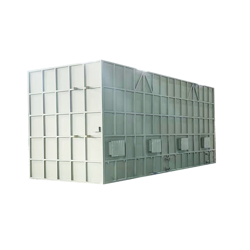
Chamber design directly impacts gas purification efficiency through two mechanisms: residence time (how long gas contacts active surfaces) and flow uniformity (avoiding channeling or dead zones). Optimal chamber length-to-diameter ratio ranges from 2:1 to 4:1 for cylindrical vessels, with baffle plates ensuring laminar to transitional flow (Reynolds number 2,000-8,000).
- Horizontal flow chambers: Better for particulate-laden streams; easy access for media replacement. Typical residence time 0.8-1.5 seconds.
- Vertical upflow chambers: Preferred for biological treatment or wet scrubbers; reduced footprint. Residence time 1.0-2.0 seconds.
- Multi-stage chambers: Series configuration with intermediate sampling ports allows performance monitoring at each stage.
A food processing facility replaced a poorly designed single-pass chamber (residence time 0.3 seconds, efficiency 72%) with a three-stage horizontal chamber (residence time 1.8 seconds, baffle plates every 2 meters). VOC removal increased to 96%, and odor complaints dropped by 89%.
| Chamber Type | Residence Time (sec) | Efficiency Range | Best Application |
|---|---|---|---|
| Single-pass horizontal | 0.5-1.0 | 70-85% | Low concentration, stable flow |
| Multi-stage horizontal | 1.2-2.0 | 90-97% | Variable load, high efficiency required |
| Vertical upflow | 1.0-1.8 | 85-95% | Limited footprint, wet scrubbing |
| Packed tower | 1.5-3.0 | 92-99% | High VOC concentration, chemical absorption |
Filtration and Adsorption Modules: Core Purification Technologies
Waste gas treatment systems employ up to four stages of filtration and adsorption. The selection depends on contaminant type, concentration, and regulatory limit. Common configurations include:
A wastewater treatment plant replaced single-stage carbon adsorption (3,000 kg carbon monthly, 85% efficiency) with a two-stage system: pre-filter + dual carbon beds (each 1,500 kg) operating in series. Efficiency improved to 97%, and carbon life extended from 30 days to 55 days, saving 28,000 USD annually.
Energy Consumption Efficiency: Optimizing Operating Costs
Energy typically represents 60-75% of lifetime operating costs for waste gas treatment. Optimization strategies target fan power (which varies with cube of airflow) and thermal oxidation (if incineration is used). Key metrics include specific energy consumption (kWh per 1,000 m³ treated) and pressure drop across media.
40-60%
Fan power reduction via VFD
0.8-1.2
kWh/1000m³ (carbon only)
15-25%
Energy savings with heat recovery
Variable frequency drives (VFDs) on main fans adjust airflow to match process batch cycles. A coatings manufacturer operating 24/7 with constant fan speed (45 kW) switched to VFD control, reducing average power to 28 kW and saving 149,000 kWh annually. For thermal oxidizer systems, installing a primary heat exchanger recovers 50-70% of exhaust heat, lowering auxiliary fuel consumption by 30-50%.
- Low pressure drop design: Select carbon with larger particle size (4-6 mm) and limit bed depth to 0.6-1.0 meter. Maintain pressure drop below 1,500 Pa.
- Demand-based operation: Use online VOC monitors to modulate fan speed and bypass airflow during low-production periods.
- Motor efficiency: Specify IE3 or IE4 premium efficiency motors for all fans and blowers.
Material Corrosion Resistance: Ensuring Long Service Life
Waste gas streams often contain acidic components (H2S, HCl, SO2), alkalis (NH3), or moisture that rapidly degrades carbon steel and aluminum. Corrosion-resistant material selection is critical for equipment exceeding 5-year design life. The table below shows standard material grades for different exposure conditions.
| Component | Mild Corrosion (pH 5-9) | Moderate Corrosion (pH 3-5) | Severe Corrosion (pH under 3) |
|---|---|---|---|
| Chamber housing | 304 Stainless steel or coated carbon steel | 316L Stainless steel | FRP or Hastelloy C-276 |
| Ductwork | Galvanized steel with epoxy coating | 316 Stainless steel | PP or PVDF plastic |
| Fan impeller | Aluminum or painted steel | 316 stainless steel | PTFE-coated or titanium |
| Carbon steel vessel | 2-3mm corrosion allowance + epoxy | 3-5mm allowance + rubber lining | Not recommended; use FRP |
A chemical plant treating HCl-laden air (pH 2.5) initially used 304 stainless steel chambers. After 18 months, pitting corrosion caused leaks and efficiency loss. Replacement with 316L stainless steel and PTFE-coated internal baffles extended service life beyond 8 years with no measurable corrosion. For high-temperature corrosive streams (over 80°C), ceramic-lined or silicon carbide materials are specified.
Integrated System Design: Bringing It All Together
The most effective odor and organic waste gas treatment equipment integrates all five parameters into a cohesive design. A case study from a pharmaceutical intermediate plant illustrates best practices:
- Problem: 25,000 m³/h exhaust at 1,200 ppm VOCs (ethanol, acetone) and 50 ppm H2S, pH 4.5, temperature 45°C.
- Solution: Pre-filter (F7) + two-stage activated carbon adsorber (each 3,000 kg, 4 mm pellet) + final HEPA. Horizontal chamber providing 1.6 sec residence time. 316L stainless steel construction with epoxy-coated ductwork. 37 kW fan with VFD control.
- Results: Outlet VOC below 20 ppm (98.3% removal), H2S below 1 ppm (98% removal). Energy consumption 1.05 kWh/1000m³. Carbon replacement every 8 months. Equipment life projected at 12 years.
Summary: Effective odor and organic waste gas treatment demands precise airflow sizing (avoid ±20% errors), chamber design ensuring 0.5-2.0 second residence time with uniform flow, multi-stage filtration (pre-filter + carbon or biofilter), VFD-driven fans for energy efficiency, and corrosion-resistant materials matching the specific gas chemistry. Facilities following these guidelines achieve consistent 95-99% removal efficiencies, 25-40% lower energy costs, and equipment longevity exceeding a decade. For application-specific engineering support, review Odor/organic waste gas treatment equipment specifications to match your exact emission profile.